Hi! I am Xiang and now using ASPECT to run some small tests. Recently I am testing how a spherical hot material in the deep mantle will contribute to the surface dynamics topography when a plate boundary is on the top. I use Visco Plastic section but only include radial viscosity variation and set the plate boundary material’s maximum and minimum viscosity to around 1e20:
set Model name = visco plastic

subsection Visco Plastic


# reference stuff
set Reference temperature =   1573
#set Reference viscosity   =   1.0e21
set Minimum strain rate   =   1.e-20
set Adiabat temperature gradient for viscosity =   9.24e-09 # 0.3 K/km
#set Adiabat temperature gradient for viscosity =   0 # 0 K/km


# Set up phase transitions so that dislocation becomes inactive in the lower mantle for all fields.
set Phase transition depths           =   background: 100e3|660e3 , plbd: 100e3|660e3
set Phase transition widths           =   background: 1e3|1e3 , plbd: 1e3|1e3
set Phase transition temperatures     =   background: 1573|1573, plbd: 1573|1573
set Phase transition Clapeyron slopes =   background: 0|0, plbd: 0|0


# Viscosity cut offs
set Minimum viscosity   =   background: 1.0e18|1.0e18|1.0e19, plbd: 0.99e20|0.99e20|0.99e20
set Maximum viscosity   =   background: 1.0e23|1.0e23|1.0e24, plbd: 1.01e20|1.01e20|1.01e20


# density-related parameters (crust has mantle density = 3300 at T = 273 K)
set Thermal diffusivities  =   1.e-6
set Heat capacities        =   750
set Densities              =   background: 3300|3300|3300, plbd: 3300|3300|3300
set Thermal expansivities  =   3e-5


# viscosity-related parameters
set Viscous flow law            =   diffusion
#set Viscous flow law            =   composite
set Viscosity averaging scheme  =   geometric

# None of this matters for plate boundaries, which we already pegged above at 1e20
# dislocation creep (just z < 660 km)
# We set the prefactor to a very low value in the lower mantle to effectively turn off dislocation creep.
set Prefactors for dislocation creep          =   background: 1e-40|1e-40|1e-40 , plbd: 1e-40|1e-40|1e-40

set Stress exponents for dislocation creep    =   3.0
set Activation energies for dislocation creep =   480.e3
set Activation volumes for dislocation creep  =   background: 0.0|0.0|0.0 ,  plbd: 0.0|0.0|0.0

# diffusion creep, (gives lower/upper mantle viscosity = 100)
set Prefactors for diffusion creep              =   background: 4.58017051e-11|5e-21|5e-23| , plbd: 4.58017051e-11|5e-21|5e-23|
set Stress exponents for diffusion creep        =   1
set Grain size exponents for diffusion creep    =   0
set Activation energies for diffusion creep     =   background: 300e3|0|0 , plbd: 300e3|0|0
set Activation volumes for diffusion creep      =   background: 0|0|0 ,  plbd: 0|0|0

# Plasticity parameters using drucker-prager
# Lower mantle - turn off using high cohesion
# Upper mantle - turn on by using 200 MPa
set Cohesions                   =   background: 1e20|1.0e20|1.0e20 , plbd: 1e20|1.0e20|1.0e20
#set Cohesions                   =   background: 20.e6|20.e6,   plbd: 20.e6|20.e6
#set Angles of internal friction =   0.0  # Friction coefficient of ~0.6
#set Maximum yield stress = 1e12

end
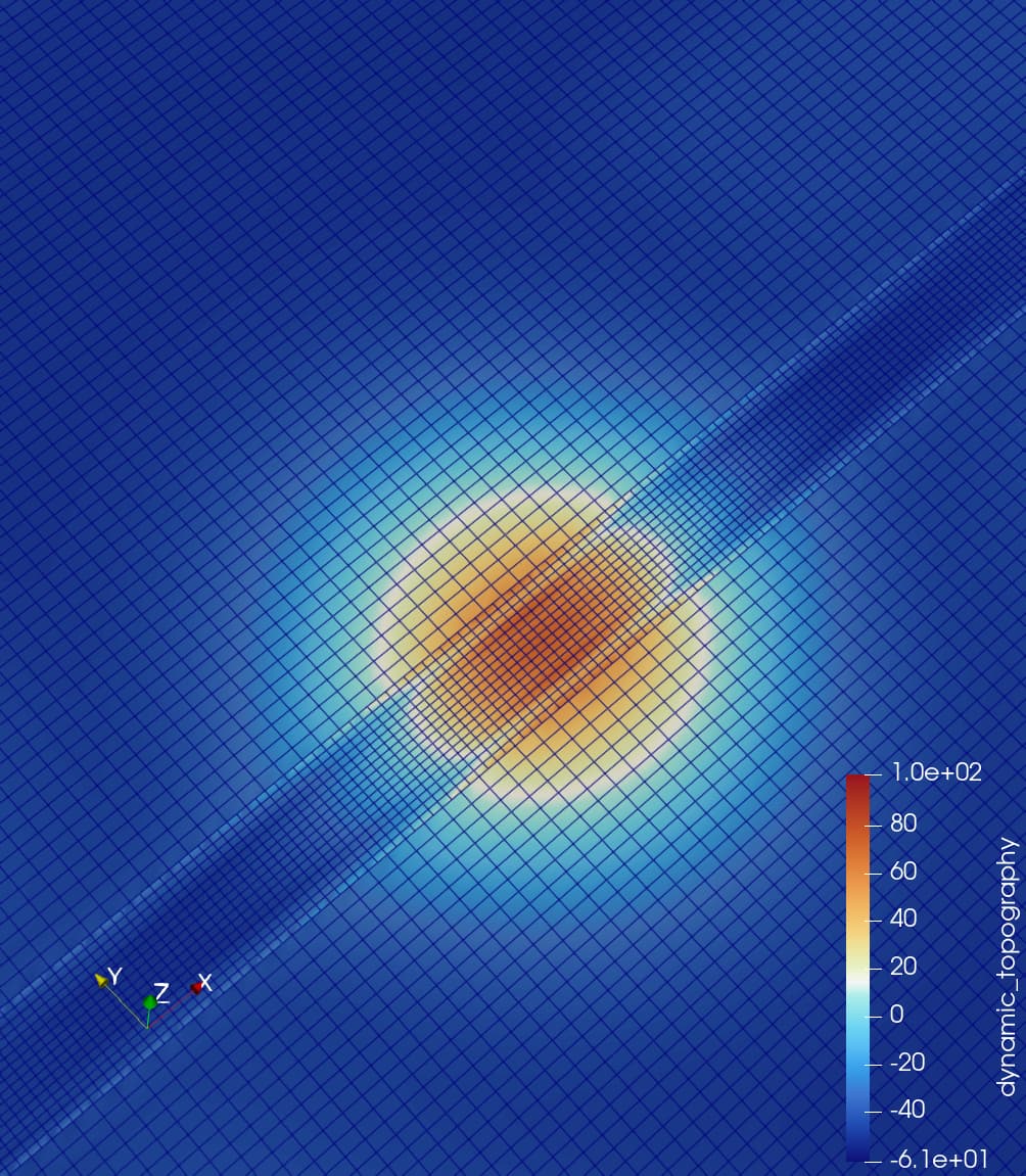
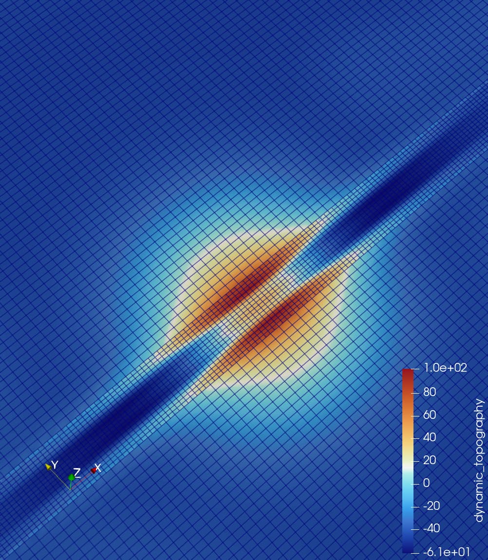
The question is, viscosity average scheme: geometric and harmonic show different reults for the top dynamics topography, even at the step 0 (I use no advection, single stokes to solve this) Does anyone have some ideas for this?
Harmonic:
Geometric

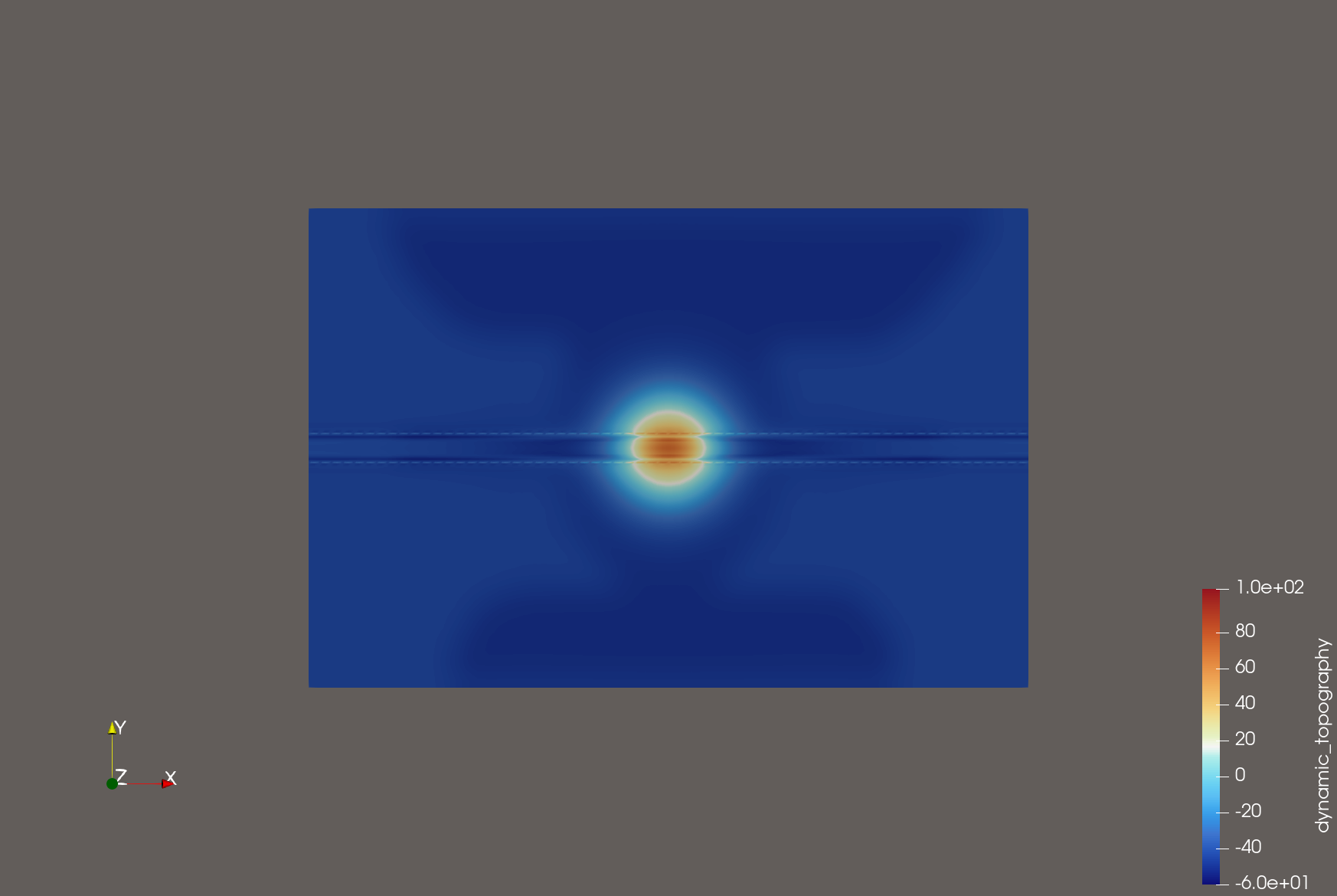
Spherical hot anomaly beneath lithosphere

Geometric.prm (10.7 KB)
Harmonic.prm (10.7 KB)
Thanks for your time!
Best regards,
Xiang He