I’m experiencing unrealistically high velocities and topography uplift rates in my 3D subduction model, and would appreciate your insights on parameter tuning.
The issues:
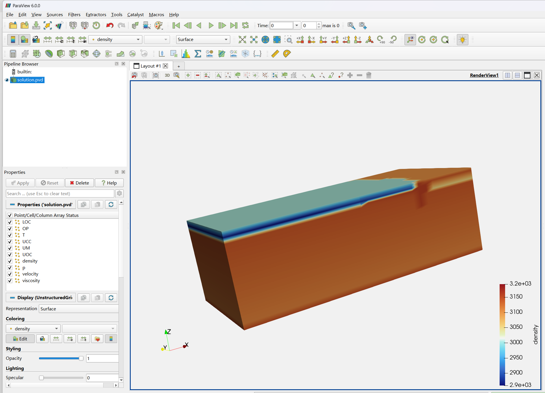
Surface velocities reaching 1-5 m/year (should be cm/year scale)
Topography uplift of 6551 meters in just 2067 years
Extremely slow computation: 9 timesteps take ~3 hours using mpirun -np 6 ~/aspect/aspect-release subduction.prm
My current setup:
ASPECT version: 3.1.0-pre
3D box: 4000×1000×1000 km
Free surface enabled with pressure normalization = “no”
World Builder for initial conditions with subduction geometry
Multicomponent material model with 5 compositional fields
Viscosities: 1e20-1e24 Pa·s
Densities: 2800-3350 kg/m³
Boundary conditions: Fixed temperature (top=273K, bottom=1573K), all boundaries tangential
What I’ve already checked/adjusted:
Increased viscosities by 1-2 orders of magnitude
Verified density contrasts and gravity (9.81 m/s²)
Switched from GMG to AMG solver
Specific questions:
What could be causing these excessive velocities without explicit boundary driving forces?
Are my viscosity values (1e20-1e24 Pa·s) still too low for realistic mantle/plate behavior?
Are there issues with my solver settings that might contribute to both the unrealistic physics and slow computation?
The combination of unrealistic physics and very slow computation suggests I might have fundamental parameter issues. Any guidance on which parameters to prioritize for tuning would be extremely helpful.
Do you prescribe initially topography to the surface or is everything flat? I think what is likely happening here is that the surface is not isostatically adjusted initially, so for the first few timesteps you will get high velocities and large adjustments in topography, after which things will stabilize and begin to evolve normally. Does the model crash during this adjustment? For more stability, I would add this to your prm file
set Maximum relative increase in time step = 50
Unfortunately there is at the moment no way to automatically account for isostatic adjustments during initialization and add it to the model. If you don’t plan to change the plate thicknesses much, a good option would be to run model for 100-1000 years when the adjustment phase is over and restart other models from there.
You mention you switched from gmg to amg, did this speed up the model? For previous models I’ve done, I found that using gmg in 3D significantly sped up the non-linear convergence for this adjustment phase.
Also, how many degrees of freedom are within the model? I would expect that 6 cores in 3D would be a limiting factor, and when you increase this to ~50k dof per core this adjustment phase may not be as much of a problem.
Hi Derek,
Thank you so much for your detailed and helpful response, I really appreciate you taking the time to share your insights. Apologies for my slow reply.
I tried switching to GMG as you recommended, but encountered Stokes solver convergence errors. After investigating, I believe the viscosity settings in my material model were problematic, I’m currently revising these parameters to improve numerical stability.
If you are using free surface, this might not be abnormal. You need to wait several steps for the topography adjustment. After the adjustment, the surface velocities will become normal.
By the way, 6 cpu cores seem not enough for 3D model, and this is why it is so slow. You need to increase the number of cpu cores, such as 128 or more cpu cores.
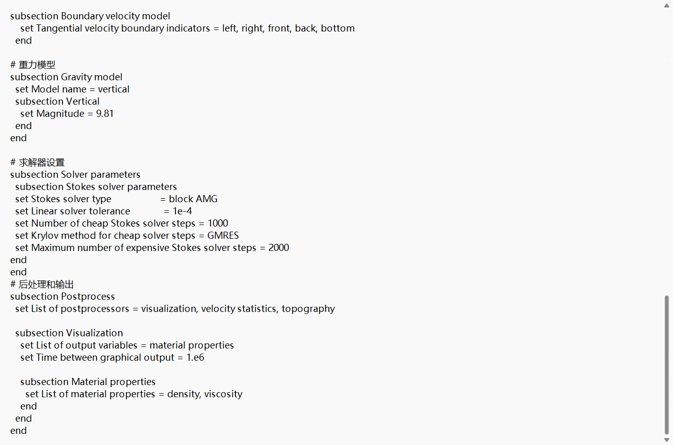
In addition, I think CFL number 0.2 and linear solver tolerance 1e-4 might lead to surface oscillation. With my experience, CFL number 0.05 (or even smaller, 0.04, 0.025), linear solver tolerance 1e-7 ~ 5e-7 and surface diffusion coefficient 1e-8 ~ 1e-6 can ensure a stable surface. However, this means very slow computation.
I followed the suggestions to adjust the CFL number and Hillslope transport coefficient, and they did help improve the topographic relief. However, I noticed that my model only has inflow but no outflow, so I revised the boundary velocity section. I also found appropriate viscosity parameters from relevant literatures. Despite these modifications, the time step (dt) has become extremely small, and the topographic relief has turned unusually large. I suspect the issue might lie in the viscosity settings. Could you please help me identify where the problem is? Thank you sincerely.
Maximum viscosity 1e22 Pas is too low for oceanic plates. You can try the value as 1e23 Pas, and set the Minimum viscosity as 1e19 Pas.
In addition, if you wanna accelerate the computation, you can try to set Linear solver A block tolerance as 1e-1 and Linear solver S block tolerance as 1e-5, in the subsection of Solver parameters/Stokes Solver parameters.
Thank you very much for your helpful suggestions and for taking the time to provide detailed advice. I apologize for my delayed response.
I have adjusted the viscosity values as you recommended, setting the maximum viscosity to 1e23 Pas and the minimum to 1e19 Pas. The changes have indeed improved the convergence significantly, which I really appreciate.
That said, I’m still working on improving the subduction morphology—it currently looks somewhat unnatural, and I’m continuing to adjust the ASPECT code to better capture the dynamics.
If you have any further insights or suggestions, I’d be very glad to hear them.