Dear all
I am conducting research that requires the use of a free surface in spherical shell geometry within ASPECT. During my simulations, I have noticed some unusual behavior in the surface traction results which I would like to bring to your attention and discuss.
I started by testing the free surface implementation in the 3D box model, specifically using the benchmark case from
free_surface_VE_cylinder_3D_loading.prm.
This model has a free surface on the top boundary with a traction load applied only on a quarter-circle loading region in the top corners. The traction magnitude is approximately t = \rho g h = 900 \times 9.8 \times 1000 \approx 8.82 \times 10^{6} \text{Pa} .
set Prescribed traction boundary indicators = top z: function
The rest of the boundaries are free-slip, set as:
set Tangential velocity boundary indicators = bottom, left, right, front, back
according to the standard free-slip conditions described in the ASPECT forum discussion on Free-slip boundary conditions.
In this Cartesian 3D box case, I verified the surface traction (t_i = \sigma_{ij} n_j ) behaves as expected:
- On the free surface (top), tractions are zero(t_x=t_y=t_z=0) except in the loaded region where the applied traction(t_z) matches the theoretical estimate.
- On the free-slip sides, the normal and tangential traction components correspond correctly with the expected zero tangential stresses and zero normal velocity.
I confirmed this by computing the traction vector in ParaView using the surface normal vectors and stress tensor data.


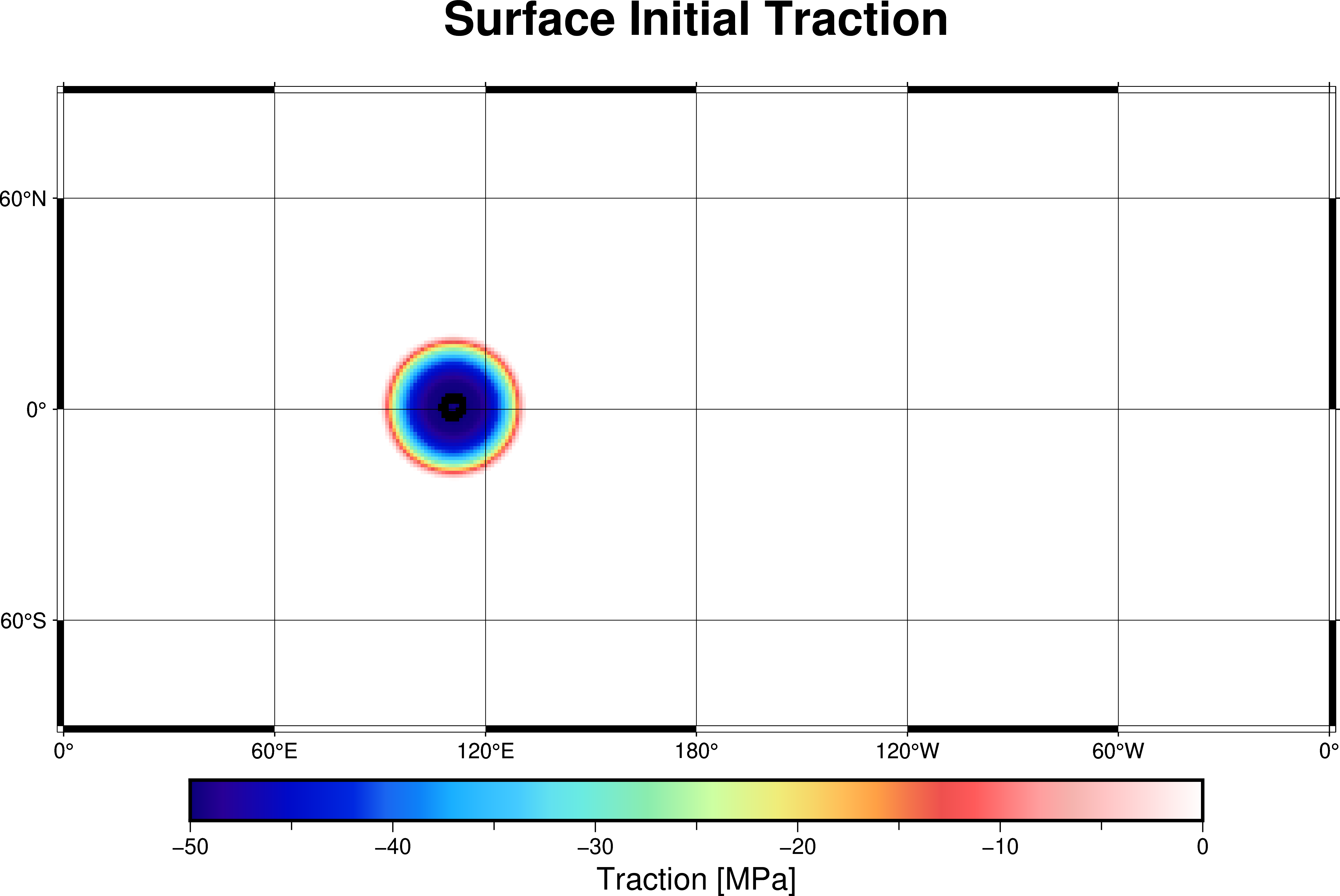
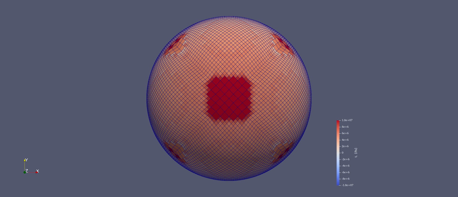
I then applied a similar procedure to a spherical shell model using a slightly modified
shell_simple_3d.prm
Using the same method in ParaView to compute the traction vector on the free surface, I found that the traction is not zero on the free surface where I expect it to be free of stress (except applied loads). This contradicts the usual free surface condition.


I am unsure whether this behavior indicates:
- An issue with how the free surface boundary conditions or traction boundary conditions are transformed and applied in spherical or non-Cartesian coordinates,
- Or if I have misunderstood some aspect of the theory or implementation. Do I need to convert from Cartesian coordinates to spherical coordinates before calculating the traction? I was under the impression that this was irrelevant.
I also tried the zero traction model and the result was the same.
This may be related to the previously opened issue Boundary traction on spherical geometries with free surface #4365, which remains unresolved.
-
Is there an established benchmark for free surface in spherical geometry within ASPECT or in the literature?
I searched for classical references but did not find a standard spherical free surface benchmark to validate this behavior. Any pointers or experience from the community would be very helpful. -
Regarding the ‘sticky air’ method benchmark from
Geophysical Journal International paper by Crameri et al. (2012), whose ASPECT benchmark repository is at
crameri_et_al,
I noticed there is no explicit sticky air test case. I wonder:- Can sticky air be implemented reliably in spherical shell or chunk models?
- Given sticky air usually requires high resolution and very low viscosity air layers, would this cause significant solver difficulties with shell-3d models?
shell_simple_3d-free_surface.prm (2.7 KB)
log.txt (13.5 KB)
Thank you very much for your attention and any insights.
Best,
Ninghui Tian