Hi Brad,
I want to know the strike and dip of vertices on fault. And I obtain the *_info.h5 file about these informations. But I can’t figure out the values, for example, there is array with 339 rows and 3 columns in the ‘/vertex_fields/strike_dir’. The 339 rows are corresponding to the number of all vertices. Do the 3 columns represent the x, y, z directions? And these values in the range of -1~1 don’t looks like angles.
Thanks.
The strike_dir vector is the direction of the along-strike vector in global coordinates. The components will be in the range [-1, 1]. If the fault strike is aligned with the x-coordinate direction the strike_dir will be (1, 0, 0). If the fault strike is aligned with the y-coordinate direction, the strike_dir will be (0, 1, 0). The dip_dir is the direction of the dip vector in global coordinates. A vertical fault with have an dip_dir of either (0, 0, 1) or (0, 0, -1), depending on the direction of the fault normal. You can compute the fault strike and dip angles from these vectors.
Thanks,I’ll try it.
Hi Brad,
I add three fault in my 3d model using planar fault for simplicity (the first picture). And the simulation with the single gyf fault can run to completion when I set the friction coefficient to 0 and don’t specify the buried edge. Whereas, the simulation with single klf or lmsf fault and no specified buried edge can’t run, the nonlinear residual norm can’t converaged and become larger and larger. Why does the planar fault also have the kind of problem? I try to reduce the time step and smooth the fault surfaces according to your advice, but it doesn’t work.
I figure the slip rate of the gyf fault along strike. Then I find the location of fault nodes changes after run the simulation (the second picture). Then, I try the simulation with specified buried edge, the node location doesn’t change. Is this the problem with the buried edge? The slip on the fault will decrease if I specify buried edge, so I don’t want to specify it. How to fix it?


Thanks.
Chen
From your diagram, I am unable to determine the geometry for each fault. Do the faults klf and gyf cut through the entire domain (all edges are on the boundaries of the domain)? If so, then this is probably the source of the problem.
Are you sure this is a reasonable boundary value problem to solve to answer your science question? Normally, we solve boundary value problems with the fault embedded in the middle of the domain to avoid undesirable affects from truncating the boundary.
Hi Brad,
The klf and gyf do cut through the entire domain. and I don’t specify the buried edges in *.cfg file. The fault edges are on the the boundaries of the domain, and the nodes of faults are removed from the nodes of Dirichlet boundary conditions. I also increase the domain aera, but it doesn’t work.
Thanks
What do you mean by “I also increase the domain but it doesn’t work”? Did you increase the domain while keeping the fault the same size and moving all boundaries several fault lengths away (you will need to add buried edges)? What specifically doesn’t work?
Sorry, I didn’t make myself clear. I just increase the distance between the faults and all boundaries about a lmsf length away, and extend the fault lengths to cut through the domain. It doesn’t work means that the same error occurs, namely that the nonlinear residual norm can’t converaged.
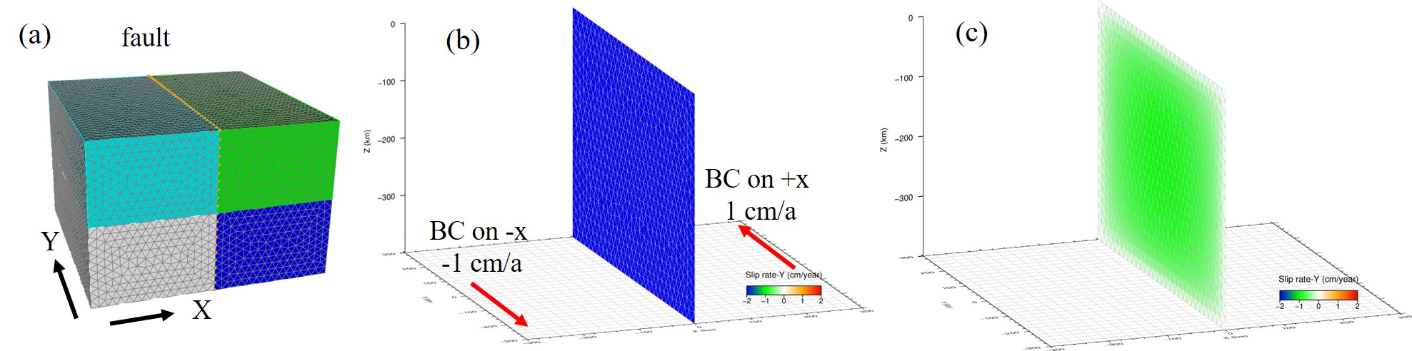
I don’t want to specify the buried edge. because it will reduce the slip on the fault. I tested the example in “3d/hex8/step12.cfg” using the 0 friction coefficient (figure a). As shown in figure (b), the velocity bc is imposed on -x and +x faces with 1 cm/a (along the Y direction). If the buried edges aren’t specified, the slip rate on fault is 2 cm/a along the Y direction, which is reliable. When the buried edges are specified, the slip rate will decrease shown in figure (c).
I slove my science question by referring to the Hergert and Heidbach (2010). They obtain the velocity bc from the GPS observation and use a small domain. If I increase the domain area, then physical properties of the increased area (e.g. elastic parameters ,viscosity or other faults in the increased area) between the boundaries and my focus area (near fault) may influence the slip on the fault and the modeled GPS velocity.
Thanks, Brad.
I think I understand what you are trying to do now. It sounds like you are trying to create a something analogous to a “block model” to determine slip rates based on free slipping (zero friction) faults. Through-going faults may be appropriate in such a case.
When using PyLith v2, the code users an iterative scheme to try to match slip with the friction value. The iterative scheme is most efficient when the fault is small and embedded in the middle of the domain. It is least efficient (requires many nonlinear solver iterations) when the fault is through-going. This means a large number of nonlinear iterations will be required.
Please post the current solver settings (preconditioner, tolerances, etc) that you are using. This problem may require a greater separation of the tolerances to ensure convergence of the nonlinear solver than a simpler problem. I also recommend using a coarser mesh to resolve the problem setup and then increase the resolution once the issues are resolved.
Yes,I want to evaluate the slip rate using free slipping faults. Here are current solver settings I used.
The first is the tolerance setting:
[pylithapp.timedependent]
interfaces=[klf]

[pylithapp.timedependent.implicit]
solver = pylith.problems.SolverNonlinear

# Set the type of fault interface condition.
[pylithapp.timedependent.interfaces]
#gyf = pylith.faults.FaultCohesiveDyn
klf = pylith.faults.FaultCohesiveDyn
#lmsf = pylith.faults.FaultCohesiveDyn

[pylithapp.timedependent.interfaces.klf]
zero_tolerance = 1.0e-7
zero_tolerance_normal = 1.0e-5
label = klf
id=13
#edge= klf_edge
#id=14
friction = pylith.friction.StaticFriction
friction.label = Static friction
friction.db_properties = spatialdata.spatialdb.UniformDB
friction.db_properties.label = Static friction
friction.db_properties.values = [friction-coefficient, cohesion]
friction.db_properties.data = [0.00 , 0.0*Pa]
#Initial fault tractions
traction_perturbation = pylith.faults.TractPerturbation
traction_perturbation.db_initial = spatialdata.spatialdb.UniformDB
traction_perturbation.db_initial.label = Initial fault tractions
traction_perturbation.db_initial.values = [traction-shear-leftlateral, traction-shear-updip, traction-normal]
traction_perturbation.db_initial.data = [0.0*MPa,0.0*MPa, -5*MPa]

quadrature.cell = pylith.feassemble.FIATSimplex
quadrature.cell.dimension = 2
quadrature.cell.quad_order = 2
The second is solver settings:
[pylithapp.petsc]
friction_pc_type = asm
friction_sub_pc_factor_shift_type = nonzero
friction_ksp_max_it = 25
friction_ksp_gmres_restart = 30
# Uncomment to view details of friction sensitivity solve.
#friction_ksp_monitor = true
#friction_ksp_view = true
friction_ksp_converged_reason = true

# Preconditioner settings.
sub_pc_factor_shift_type = nonzero
# Convergence parameters.
ksp_rtol = 1.0e-20
ksp_atol = 1.0e-8
ksp_max_it = 5000
ksp_gmres_restart = 100
# Linear solver monitoring options.
ksp_monitor = true
#ksp_view = true
ksp_converged_reason = true
ksp_error_if_not_converged = true
# Nonlinear solver monitoring options.
snes_rtol = 1.0e-20
snes_atol = 1.0e-4
snes_max_it = 500
snes_monitor = true
#snes_view = true
snes_linesearch_monitor = true
snes_converged_reason = true
snes_error_if_not_converged = true
# End of file
I also tried the preconditioner you adviced in src/pylith-2.2.2/share/settings/solver_fault_fieldsplit.cfg. It didn’t solve the nonconvergence problem of the nonlinear residual norm and run slower much than the ASM preconditioner, so I don’t use it. I can provide more information if you need. By the way, does the Pylith v3 solve the problem with static friction better? Thanks, Brad.
I think you need to tighten the absolute solver tolerances. I would try
# use the same values for all faults
[pylithapp.timedependent.interfaces.klf]
zero_tolerance = 1.0e-10

[pylithapp.petsc]
ksp_atol = 1.0e-12
snes_atol = 1.0e-8

# Add this setting
ksp_monitor_true_residual = true
If this doesn’t work, please capture ALL of the output to stdout to a log file and upload it. The first step is to verify that the linear solve is converging properly. The second step is to get the nonlinear solve to converge.
If the ASM preconditioner is faster, then it might be okay. I would check whether the custom preconditioner settings results in faster run times with these tighter tolerances.
Hi, Brad. I updated the 3d model shown as follows and set the absolute solver tolerances according to your advice.
When I used the ASM preconditioner, I changed the zero_tolerance_normal to 1.0e-1 and still got the error of RuntimeError: WARNING! Fault opening with nonzero traction., v_fault: 2173, opening: 0.0101055, normal traction: 7.6532e-08. Whereas, the simulation can run to completion when I specify the buried edge. Here is the part of slover setting and log.txt using the ASM preconditioner.
[pylithapp.petsc]
friction_pc_type = asm
friction_sub_pc_factor_shift_type = nonzero
friction_ksp_max_it = 10000
friction_ksp_gmres_restart = 30
friction_ksp_monitor = true
friction_ksp_view = true
friction_ksp_converged_reason = true
ksp_monitor_true_residual = true
log_asm.zip (3.9 MB)
When I used the fieldsplit preconditioner, I got the error of PETSC ERROR: KSPSolve has not converged. Here is the part of slover setting and log.txt using the fieldsplit preconditioner.
[pylithapp.problem.formulation]
split_fields = True
matrix_type = aij
[pylithapp.petsc]
fs_pc_type = fieldsplit
fs_pc_use_amat = true
fs_pc_fieldsplit_type = multiplicative
fs_fieldsplit_displacement_pc_type = ml
fs_fieldsplit_lagrange_multiplier_pc_type = jacobi
fs_fieldsplit_displacement_ksp_type = preonly
fs_fieldsplit_lagrange_multiplier_ksp_type = preonly
log_fieldsplit.txt (838.9 KB)
Thanks.
